
By Adrian David Cheok, Kasun Karunanayaka, Halimahtuss Saadiah, Hamizah Shahroom
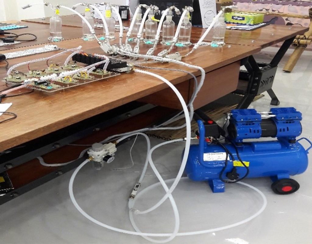
Many of the Olfactometer implementations we find today, comes with high price and they are complex to use. This project aiming to develop a simple, low cost, and easily movable laboratory Olfactometer, that can be used as a support tool for wider range of experiments related to smell, taste, psychology, neuroscience, and fMRI. Generally, Olfactometers use two types of olfactents; solid or liquid odor. Our laboratory Olfactometer (as shown in Figure 1) will support for liquid based odors and later we may also extend to handle solid odors. Also we are thinking of improving this system as a combined Olfactometer and Gustometer.
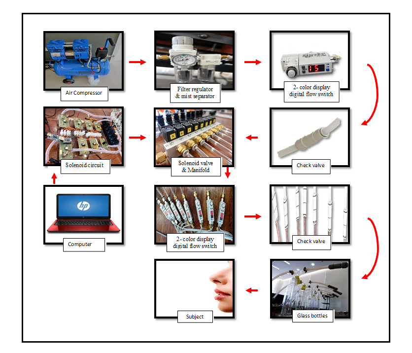
In this Olfactometer design, we utilize continuous flow (Lorig design) for good temporal control. Lorig design have simpler design and low cost due to minimal usage of parts as compared to other designs (Lundstrom et al., 2010). Our Olfactometer contains an 8 output channels that will produces aromas in a precise and controlled manner. Besides that, it also produces a constant humidified flow of pure air. The laboratory Olfactometer components consists of oil less piston air compressor, filter regulator & mist separator, 2- color display digital flow switch, check valve, solenoid, manifold, TRIVOT glass tube, connector, gas hose clip and also PU tubing. The controlling system of Olfactometer will consists of Adruino Pro mini, UART converter, USB cable and solenoid circuit.
Air supply from oil-less piston air compressor plays an important part to deliver the odor with a constant air pressure to the subjected nose. After that, the filter regulator combined with mist separator are used to ensure the air is clean and did not have any other contaminant. After the filter, the air flows will be metered through to 2-color display digital flow switch. Check valves are connected after the flowmeter to ensure that the air will flow only in one direction. After the check valve, the tube is then connected to 9 fitting male connectors which directly fit into the 8 output of manifold. Then, 8 pcs of normally closed solenoid valves will be connected to the top of the manifold. The Olfactometer can manually be controlled by computer to send an odour to the nose. A 2-color display digital flow switch will be connecting after solenoid to make sure the air will flow around 3 LPM to 5 LPM (to avoid any discomfort to the subjected nose). If the solenoid valve is on by computer, the air will pass through to the glass bottles and proved it by seeing the bubbling air inside of glass bottles. Finally, air flow will blow the liquid/solid and go through the check valve before straight to human nose.
References:
Johan N.Lundstrom, Amy R.Gordon, Eva C. Alden, Sanne Boesveldt, and Jessica Albrecht. Methods for building an inexpensive computer-controlled Olfactometer for temporally precise experiments (2010).
Bradley N. Johnson and Noam Sobel. Methods for building an Olfactometer with known concentration outcomes (2006).